


Not Sure which hinge to use? we are here to help.
Door Hinge Drilling Patterns
TEMPLATE ‘ANSI’ (most common) ZIG ZAG ‘congruent’ STRAIGHT
Door Hinge Spacing and Selection Information
Selecting the right hinge by door weight alone is bad practice. With the help of Carlisle Brass, we have put together a simple guide on hinge selection in order to help you select the right hinge for your project. In order to ensure the correct hinge is specified, you need to understand the intended use of the building and calculate the overall door mass accordingly. The overall door mass includes, door weight, allowances for frequency of use, excess width side loading, the inclusion of door closers and all other door hardware. Follow the simple code of practice to correct hinge specification - if in doubt, you can contact us for a quote on providing a full design service.
| Calculate Door Weight to Actual Door Mass | |||
|
ACTUAL DOOR WIDTH |
Doors with excessive width, refer to “Side Loading Calculation Table” | + ?% |
=ACTUAL DOOR MASS |
| Door closer | +20% | ||
| Door closer (incorporating back check or hold open facility) | +75% | ||
|
Light usage application Extra heavy usage application |
-10% +10% |
||
| Side Loading Calculation Table | ||||
| CALCULATE EXCESSIVE DOOR WIDTH | DOOR HEIGHT (MM) |
DOOR WIDTH (MM) |
FACTOR | INCREASE IN DOOR MASS REQUIRED |
|
The actual door mass will require increasing by the factor This is calculated by dividing the door height by the door If the factor is larger than 2, there is no allowance required. If the factor is less than 2, the door mass is required to be Percentage examples are listed in the table to the right.
|
2000 | 1000 | 2.00 | 0% |
| 2000 | 1050 | 1.90 | +10% | |
| 2000 | 1100 | 1.82 | +18% | |
| 2000 | 1150 | 1.74 | +26% | |
| 2000 | 1200 | 1.67 | +33% | |
| 2000 | 1250 | 1.60 | +40% | |
| 2000 | 1300 | 1.54 | +46% | |
Door Hinge Spacing: Code of practice
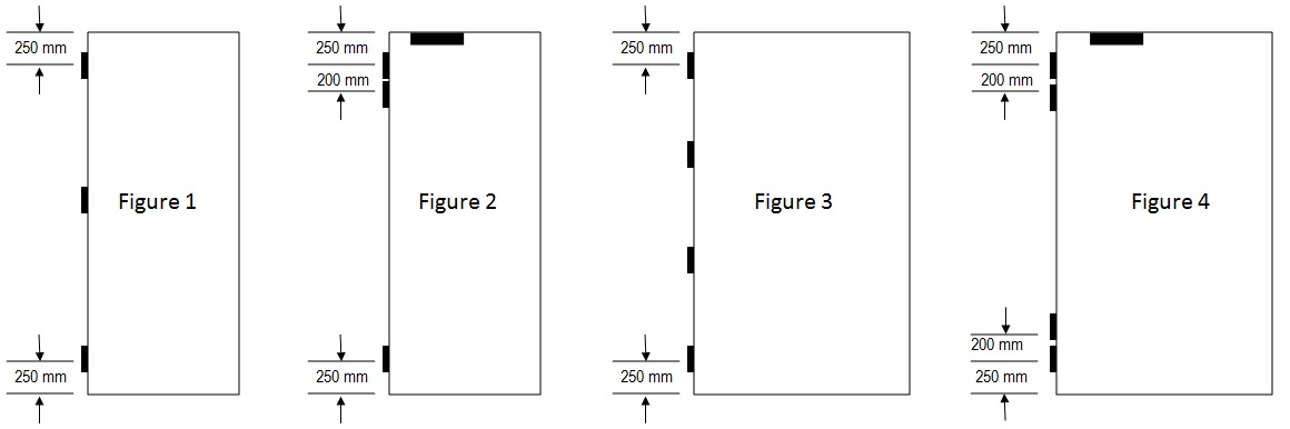
FIGURE 1: The standard practice and most common, providing maximum resistance to ‘warping’, hinges are spaced as shown.
FIGURE 2: Where overhead door closers are used, additional lateral forces are applied to the top hinge. Whilst this is taken into consideration within the design calculation, to reduce the lateral force to the top hinge, it is recommended that the hinges are spaced as shown.
FIGURE 3: Where the door width is more than 1000mm or the door mass exceeds that allowed for 3 hinges, additional hinges can be fitted. Equal spacing shown provides maximum resistance to ‘warping’, based on 4 hinges, the design door mass can be calculated as per ‘side load calculation’ table before determining the suitable grade of hinge.
FIGURE 4: Where overhead door closers are used within the example illustrated in Figure 3, due to the increased lateral forces created by the closer on the top hinge, it is recommended that the hinges are spaced as shown.